Engineering Circuits Analysis (DC)
Table of Contents
- Table of Contents
Introduction
Voltage, Current, Resistance
- Circuit: Closed loop that carries electricity
- Current (real life current): flow of electrons in a circuit (the negative charge is the one moving towards the positive source)
- hole current (engineering current “i”): Mathematically it is equivalent to assume that it’s the positive side charge the ones that is moving from the positive source to the negative source, and it makes the equations simpler as opposed to having to deal with negative signs, so we use the positive charge instead.
- Unit: Ampere (Amp, A): how many charges are moving through the circuit per unit of time.
- Analogy: if you blow a straw, the air is the current, it is what is moving through the straw
- Current comming directly from the source is sometimes labled \(i_s\)
- Voltage: The “push” that causes the current to flow. It’s the source. It’s very related to the current. You cannot have any current without having something pushing it.
- Analogy: The voltage is the push pressure from the blow. A high voltage as a high potential to push a lot of current, but the push itself is not what kills you, what would kill you is the current.
- Resistance: Opposes current flow in a circuit. It makes it harder to blow the same amount of air. The smaller the object the higher the resistance.
- Unit: Ohm, \(\Omega\)
- Resistors in sequence are equivalent to 1 resistor with the resistance combined
- Direct current (DC): i.e. batteries, its source gives a constant voltage (which causes constant current)
- Alternating current (AC): i.e. wall socket, the current moves back and forth.
- Open circuit: a broken circuit and therefore there is no more current flow.
- Short circuit: circuit that (accidentally) gets shortened and creates a path of small resistance back to the source, which generally skips the intended meaning of the circuit and generates a lot of heat and cause a fire.
- Circuit breakers at home can detect increasing current consumption and shut its down it to avoid shortcircuits
Components: Resistor, Capacitor, Inductor, Transistor, Diode, Transformer
- Source voltage: (+ -) generic, or a battery (bunch of horizontal lines), or (~) for AC
- short horizontal line is the negative terminal
- long side is the positive terminal
- base unit is Volts
- Resistor (zig zag): limits how much current there is on a branch.
- Base unit is Ohms
- Capacitor (-||-): device that stores electric charge
- You pile it up and at a later time it lets you bleed it out to feed the circuit
- Base unit: Farad (F) measures how much energy in the form of electric field can be stored
- Inductor (like a spring) concentrates magnetic field
- Unit is Henry (H): how much energy in the form of magnetic field can be stored
- Diode ( -|>|-): only allows direct current to flow in one direction
- LED: Light Emitting Diode (same symbol but with some arrows representing the light)
- Transistors (3 wires symbol)
- It can act as a switch
- It can act as an amplifier
- Transformer: allows a voltage to change its value
- Useful to transform the wall socket voltage to a smaller voltage for light home appliances

Ohm’s Law
- V = IR
- voltage = current * resistance
- Also \(V_n = I_n R_n\) where n is the component and we are measuring with the multimeter directly at each of the component terminals
- The voltage drop of all the the circuit parts (calculated at each part with Ohm’s law) has to eventually add up to equal the source voltage.
- Ohms law allows us to see and make branches with different voltages (for components with different specs)
- passive components: are those that are not a source of power
- They have a voltage drop
- voltage drop actually means the difference between the positive and the negative terminals
Power calculations
- Unit of power is a Watt
- Watt It’s energy (i.e. joules) per unit of time (seconds) = joule/sec
- So it’s about something (energy) happening continously, i.e. “usage”
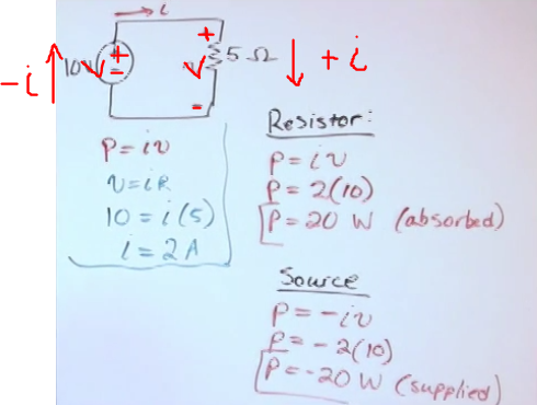
- p = iv
- the more power the hotter the component gets
- negative power means that the component is actually delivering power to the circuit
- signs of i
- if the current (i) is flowing from the positive terminal (side that its connected to the positive side of the source) to the negative terminal of the component, then i is positive at the component, else is negative (same for voltage)
- if i is negative then the power is negative, which means that the component is a source
- when the voltage comes directly from the source is the same as the source
- The power consumed by all passive components has to be equal to the power generated by all sources
- The power, measured in watts, if too high it will make the component burn
- From Om’s law (V=IR) we also have that (for passive components because it’s always positive)
- p = iv
- \(p=i^2r\)
- \(p=\frac{v^2}{r}\)
Example of sign convention of the voltage drop (ignore the signs of i in the picture (typo), what we change is the drop sign, if the cuurrent goes from - to + then the voltage drop is negative (power source) if it goes from + to - it’s possitive (passive component):
Kirchhoff’s Current Law (KCL)
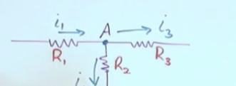
- The algebraic (sign sensitive) sum of currents at any node is zero
- node is a connection point: ___|___
- Electricity prefers to take the path of least resistance.
- Sign convention, the node itself is the “center of the universe”, we dont care about active/passive components such as the source.
- If the current leaves the node, then it has positive sign
- If the current reaches the node, then it has negative sign
- Although usually observed at nodes that connect 3+ things, two elements are also connected by a node (even if they are on the same stright line ont sequence, there is a node between every component)
- If you have n nodes you can only write n-1 independent equations. So it is not worth to write up the last node equation as that one wont be independent (just a rewriting of existing ones) and wont help solve the problem
Kirchhoff’s Voltage Law (KVL)
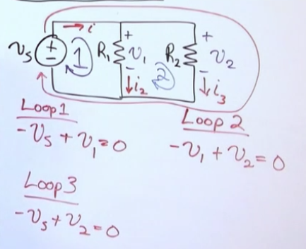
- The algebraic sum of all the voltage drops around any closed path in a circuit is zero. It doesnt regard nodes, it just regards loops.
- KVL, although uses a route path of its own for the loops, it does take the polarity of the actual currents (i.e. where the + and - terminals are) to determine the sign of the voltage drop in the KVL equation.
- If the “loop path” goes from positive terminal to negative terminal, the votlage drop is positive
- If the “current” goes from the negative terminal to the positive terminal the votlage drop is negative.
- See how R1 has a positive drop in loop 1 yet a negative drop in loop 2
-
Se how we can just take the outside loop too
-
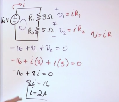
In a practical setting KVL is used in combination with Ohm’s law, so you end up rewritting KVL in terms of current * resistance:
- In complex circuits, you’ll likely exhaust the n-1 indepdendent KCL equations and you’ll suplement it with as many KVL loop equations as possible to achieve n equations for n variables. Then solve the system of linear equations with a machine (i.e. matrix solver)
- For n total loops, you can write n-1 independent equations
- There are as many loops as arbitrary closed paths without branches you can find, i.e. some of them:
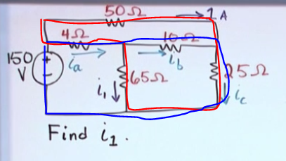
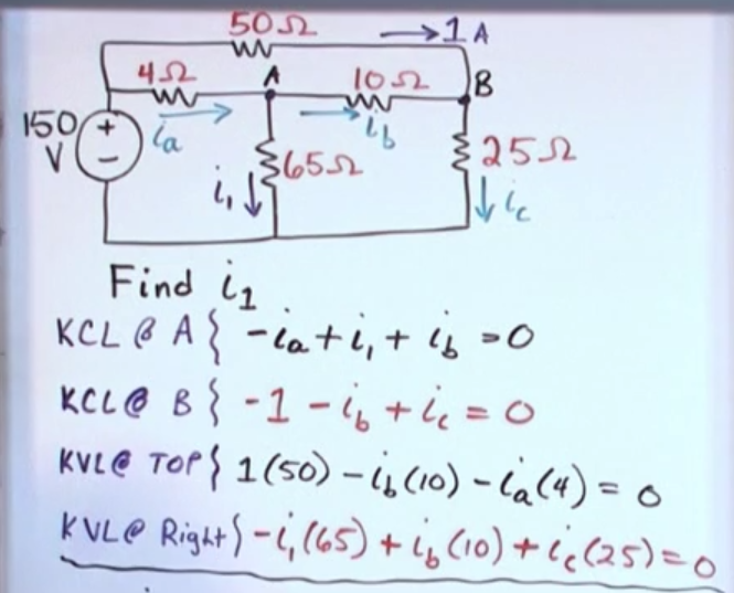
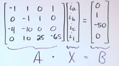
Example to solve for \(i_1\):
rref(A)
- If you want to check the voltage difference between any two points in a circuit you are allowed to create an imaginary wire to construct a KVL loop
Dependent Current Sources
- Any arrow symbol represents a current source.
- When it’s within a circle its a source that adjusts its voltage in response to the resistance in the circuit such that the emitted current is constant.
- When it’s within a diamond it is a dependent current source. That is the final amount flowing from the component is not fixed, and most importantly that depends on the behaviour of somewhere else in the circuit (i.e. a transistor triggering things).
- Independent circuits that are located close to each other and that have the same big picture type of goal are commonly connected to the same negative terminal to ensure that base voltage (difference between + and -) is consistent among all the circuits. Otherwise you might get a circuit with a base voltage of +500 and +600 vs other one with 0 and +100 located close to each other which can cause many problems. The negative terminal also regarded as ground, therefore the practice of connecting all the negative terminals to the same negative voltage source is called “grounding”.
- The voltage drop for each of the parallel branches connected to the same source is the same.
- If you get a negative current it means that the direction that you’ve drawn in your circuit is flipped.
- But you dont know to change the orientation of the drawing. Once you’ve set the drawings you can stick to the values that you have and keep going to solve for whatever you need to solve.
Measuring the circuit
Node voltage method
- It takes less equations than Kirchhoff’s laws and it’s more strict.
- It’s called voltage but it’s just the “currents” sum equal to zero
- A node is any interconnection of two or more components
- Essential node are those that have 3 or more components (the supply is a component)
- A node that connects just 2 components has the same current flowing through them so they are not relevant for the node voltage method.
- The node voltage method consists of 4 steps:
- Identify the essential nodes.
- Choose a reference node
- most of the times is the node with most connections and at the bottom of the drawing.
- When you are measuring something in a circuit with the multimieter you’re basically checking the difference in V or A or R between the black lead and the read lead.
- Write node voltage equations in reference to the reference node.
- For n number of essential nodes you need n-1 node voltage equations to completely discribe the circuit
- Once the node voltages are found, it’s very easy to find everything else.
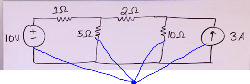
Example:
- Identify the essential nodes (we have 3 so we need 2 equations)
- Just because the bottom node is spread out it is still one node that connects several components at once
- Pick a reference node (bottom one has the most interconnections)
- The reference node is symbolized with a triangle that represents commonality or reference.
- The node voltage equations that we will find are for the two top (essential) nodes with respect to the reference node
- Se that the minus signs are the reference node such that the voltages \(v_1\) and \(v_2\) (for nodes 1 and 2 respectively) are measured in reference to the reference node.
- When you are writing the node voltage equations of an essential node you ignore the current direction of i and pretend that all i are leaving the node. (the sign of the answer will take care of everything).
- prepararation for \(\text{NV @ Node 1:}\)
- \(v_{1\Omega}=v_1-v_s\) (it’s kinda triangle KVL with source, node 1 and reference node as points of the loop, the difference is )
- \(i_{1\Omega}=\frac{v_{1\Omega}}{1\Omega}=\frac{v_1-v_s}{1}\)
- \(i_{5\Omega}=\frac{v_1}{5}\)
- \(i_{2\Omega}=\frac{v_1-v_2}{2}\)
- \[\text{NV @ Node 1:}\ i_{1\Omega} + i_{5\Omega} + i_{3\Omega} = 0,\frac{v_1-10}{1} + \frac{v_1}{5} + \frac{v_1-v_2}{2} = 0\]
- \[\text{NV @ Node 2:}\ \frac{v_2-v_1}{2} + \frac{v_2}{10} - 3 = 0\]
- Solve for \(v_1\) and \(v_2\).
- The main takeaway from the NV is that
- We write a modified KCL where we pretend that the all curents at the node are leaving and their sum equals 0
- if parallel branches (where the positive and negative terminals are connected directly to the source without resistance) have the same voltage, in the event that the terminals experience a resistance between the parallel branches, we can calculate the voltage drop from the resistance by substracting the voltages of branch A and branch B (then divide that by the resistance itself to get i (I=V/R)).
- In NV context the positive voltage is the one of the node we are writting the equation.
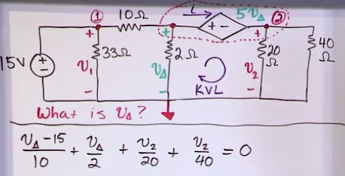
Dependent sources and supernodes
- They are labled with a romboid: <+ ->
- A source (independent or dependent) connected to two essential nodes will reduce the number of available NV equations (because generally it’s gonna be hard to find out the current of that leg if we’re just given the voltage).
- you’ll need to introduce a variable \(i_k\) into the NV equation and reuse that \(i_k\) for the other node of the source and then cancel them out.
- Or you can apply the “supernode” technique which just merges the nodes. KCL, KVL, NVL also apply two a selection of n nodes, “what comes inside the area equals what comes outside the area”
- Then apply NV to the merged node
- Then apply NV to the merged node
- Since we lost 1 equation, we need to supplement it with something else, such as a KVL or KCL.
- Another not so obvious example:
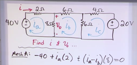
Mesh current method
- It’s a modified KVL much like NV is a modified KCL
Steps:
- Identify the meshes (polygons, squares, triangles, etc)
- The number of equations you need is equal to the number of meshes you have.
- Label the \(i_n\) of each mesh
- Write the mesh equations wiht the “net currents” that is, whenever an edge has two labled \(i_n\)’s, use the difference (and have the positive i to be the one of the given mesh equation)
- Solve the system of equations
- With the mesh currents you can find the real currents.
- You have to pay attention to the circuit, the circuit currents are either equal to the mesh currents (when they are not “fighting” with another current) or to the difference between two mesh currents (those that overlap a leg). * The take away of MC and NV is that they are direct applications of Kirchhoff’s law with a very specific algorithm to solve the problems, which generally reduces the amount of equations and sets a clear action plan to solve a problem.
Current source, Supermesh and dependent power source
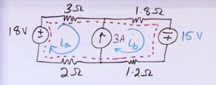
- Like in a supernode you can experience tricky problems with powersources whose current (and resistance) is unkown, here you can experience problems with current sources whose voltage (and resistance) is unkown.
- Any time you see a current source that travels two meshes you’ll either have to come up with a dummy voltage variable (that will be cancelled out) or draw a supermesh around the problem area.
- Either approach will require an additional constraint equation to solve the system, you can use the fact that the difference between \(i_a\) and \(i_b\) has got to be the amps of the (a priori problematic) current source
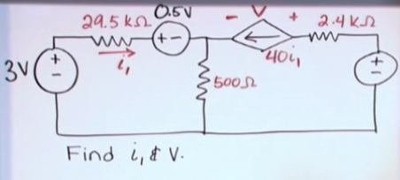
- A dependendent powersource will introduce an additional variable onto the system of equations. It can be circumvented by finding another constraint equation by means of for instance KCL involving said variable.
Equivalent Circuits
Resistors in series and Parallel
- In series is also called “daisy chaining”
- The current that flows through them remains the same. In a DC circuit the current can only change if it branches.
- The resistance of the 3 resistors is equivalent to a resistor with a resistance of their sum.
- The powersource might be in between the resistors but that’s still in series.
- Parallel resistors
- The current branches

- For 2 parallel resistors you can use:
- \[R_{eq}=\frac{R_1R_2}{R_1+R_2}\]
- These can be used to simplify circuits which will limit the complexity of the system of equations that we need to solve
- If there is a branch with 0 resistance 100% of the current is going to go towards that branch, leaving the other branches of the node unvisited.
Source transformations
- Circuit simplification of the current and voltage sources.
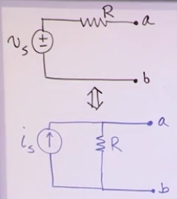
- You can rewrire a resistor in series with a power source into a circuit where the the resistor is on parallel with a current source
- What we need to find is the value of the current source with Ohm’s law
- \[i_s=\frac{v_s}{R}\]
- You can rewrire a resistor in series with a power source into a circuit where the the resistor is on parallel with a current source
- If a current source has a resistor in series, it can be ignored as the current entering the resistor is the same one leaving it, which goes unnoticed to the terminals a and b
- If a power source has a resistor in parallel, it doesnt matter to a and b either as the voltage remains the same
- The polarity of the power source has to match the direction of the current source.
Currents in parallel
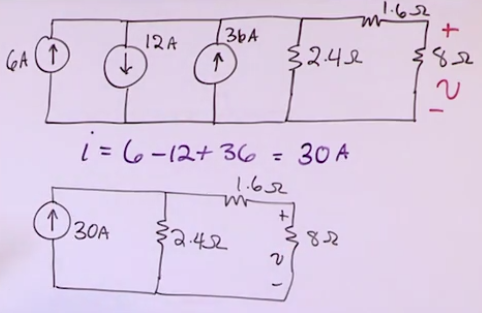
- It’s the algebraic sum of them (algebraic means that it’s sensetive to signs instead of just summing absolute values).
- Currents in series dont make sense because the value of a current source is supposed to hold for the entire leg.
Power sources in series
- They’re equivalent to a power source of the algebraic sum of them (if they are of opposite polarity, it’s gonna be the difference of them and it’ll keep the polarity of the bigger one)
- Power source in series should have the same voltage (KVL) if not the higher voltage source would be discharged onto the lower voltage source until both have the same votlage and/or will fuck things up.
Thevenin Equivalent Circuits
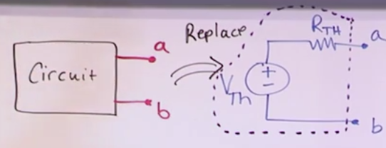
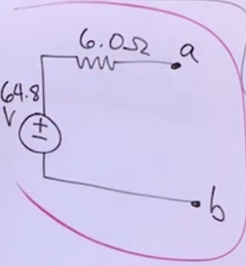
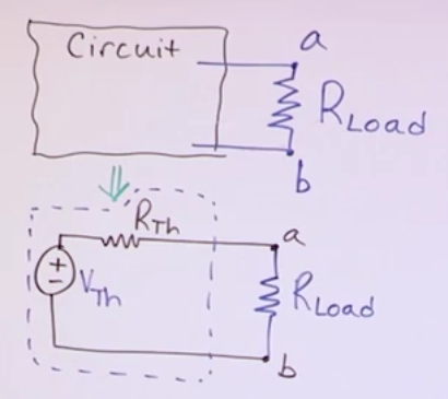
- Lets you model the entire circuit as a voltage source and a resistance.
- Any network of resistors and sources can always be rewritten in terms of a single voltage source and a single resistor.
- This also applies with inductors and capacitors in AC
Steps:
- Prerequisite: identify two terminals (a and b) from which the circuit is connected to the outside world.
- Different choice of terminals will likely result in different Thevenin Equivalent circuits.
- \(V_{th}\): Find open circuit voltage between a and b (load free voltage)
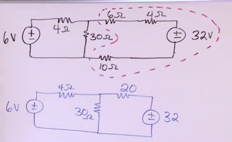
- \(R_{th}\): Find the short circuit current between a and b (called \(i_{sc}\)). Then \(R_{th}=\frac{V_{th}}{i_{sc}}\).
- You’ll find 2 and 3 probably by using Node Voltage or Mesh Voltage methods.
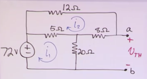
Examle:
- \(\text{MC1: } -72 + (i_1-i_2)5 + i_120 = 0\)
- \(\text{MC2: } (i_2-i_1)5 + i_212 + i_28 = 0\)
- Solve for \(i_1\) and \(i_2\) and you get 3 and 0.6 respectively.
- \(V_{th}\) (in the context of this circuit) = \(V_{8\Omega}+V_{20\Omega}\).
- = 0.6 * 8 + 3 * 20 = 64.8
- \(i_{sc}\) (in the context of this circuit) can be found by doing the mesh current process all over again with the updated circuit with the shortcircuit:
- This would yield 12.72, 6 and 10.8
- \(R_{th}=\frac{V_{th}}{i_{sc}}=\frac{64.8}{10.8}=6\)
Norton Equivalent Circuits
- Transforming a Thevenin equivalent to a current source with a resistor in parallel
Voltage divider circuits
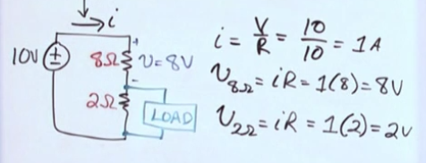
- You can use a voltage divider to use a 12V source to supply a 5V circuit
- It doesnt matter (only for the current) the size of the resistance to divide the volts, what matters is the ratio of the two resistors, that’s what determines how much voltage will go to each part.
- The 2V volts calculated are the “no load” voltage.
- Once we connect the load we are actually adding a parallel resistance with the 2 oms resistors.
- If the load is infinity (i.e. open circuit) it’s as if we didnt breanch out anything
- That’s how multieters work, by having a very large internal resistance which makes the branches of the multimeter to not interfere with the circuit.
- If the load is 0, we are creating a short circuit that skips the 2 oms resistor, so we end up with 0V and 10V in the first resistor.
- The equivalent resistance can be calculated with the 2 resistors parallel equivalence \(R_{eq}=\frac{R_1R_2}{R_1+R_2}\)
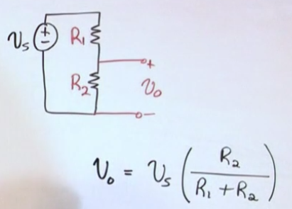
- The (no load) voltage going through that circuit can be calculated with (which is basically the same as just the voltage drop of the resistor. However we calculate without KVL or Oms law, that is, without needing to find the current and just by using the source voltage and resistances):
- If the load is infinity (i.e. open circuit) it’s as if we didnt breanch out anything
- Once we connect the load we are actually adding a parallel resistance with the 2 oms resistors.
- To calculate the actual voltage going through the loaded circuit first apply the equivalence resitance and then the voltage formula above.
- The bigger \(R_2\) the closer the no load voltage it gets to the source voltage
- The smaller \(R_2\) the closer the no load voltage goes to 0 (short circuit).
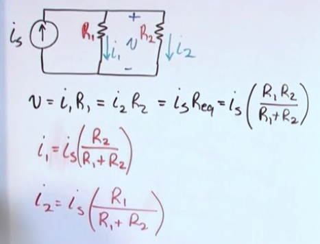
Current Divider Circuits
- This applies to circuits that have a fixed current source.
- You have to use the opposite resistance as numerator.
Maximum Power transfer
- We can model the load that we want as a resistor
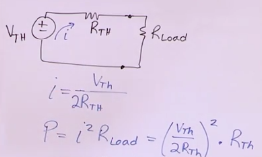
- We are looking for which value of the load resistance results in maximum power transfer from the source to the load.
- When resistance is 0, we have \(P=I^2R=I\cdot 0=0\)
- When resistance is “a very large countable integer” we can say that I approximates 0 and without giving a heart attack to mathematicians infere that \(P=I^2R=0\cdot R=0\).
- The maximum power happens when \(R_{load} = R_{th}\).
- You can manually check this by writting a function that returns the power delivered to the load as a function of resistance and set the derivative equal to 0.
- It kinda looks like a voltage divider too, in which we can see that when the value of the two the resistors are equal, then the voltage of the source is split evenly among the two resistors.
- When maximum power is being delivered whe know that \(R_{load} = R_{th}\)
- \[P_{max}=\frac{V^2_{th}}{4R_{th}}\]
Superposition
- The circuit behaves as a superposition of all the sources together (that is, the sum of all individual contributions of the sources to the circuit)
- What you do is, for each of the sources, calculate the voltage/resistance/current/etc of the element(s) that need to be analyzed as if only that source existed in the circuit, then add all the values of each source to find the final value.
- This is possible due to the “linear” nature of the circuits we’re dealing with.
- It’s a great method for troubleshooting problems with sources.
- It is also appropiate when you need to simplify the circuit, the cost is that you’ll have to repeat the process for each source
Capacitors and Inductors
Inductor (L)
- Unit: Henry (H)
- Circuit element that stores energy in a magnetic field.
- The current goes through the coil and the more turns the more the magnetic field is concentrentated.
- The more current the stronger the magnetic field
-
\[V_L(t)=L\frac{di}{dt}\]
- The voltage drop of an inductor is it’s inductance times the derivative of the current with respect to time.
- It’s not proportional to the current itself, but to how fast the current changes
- The reason this is true is because an inductor itself it’s just piece of cable without resistance, therefore a circuit with just a source and an inductor is just a shortcircuit.
- Constant current -> 0V
- Current rises -> +V
- Current decreases -> -V
- Rewritting the voltage equation yields the current equation:
- Power is still p = iv
- however p cannot be expressed with resistance as it’s 0, the alternative is to replace v(t) with di/dt so:
- \[p=i\cdot L \cdot \frac{di}{dt}\]
- We dont need to know anything about the current if we already know the voltage:
- \[p=v \left(\frac{1}{L}\int_0^t v(t)dt + i(0)\right)\]
- Recall that \(\text{power}=\frac{\text{energy}}{\text{time}}=\frac{dw}{dt}\) where “w” stands for energy (work).
- dw = pdt
- \(w = \int_0^tpdt = \text{energy}\)
- \(\text{Energy is the integral of power}\)
- \(w = L\frac{1}{2}i^2\) in jules.
- This means that energy stored in a transistor increases quadratically as the current increases. It also means that if the current is constant the stored energy is also a (constant) positive number. If current increased from 0 to k and then it remained constant at k we hare mantaining the energy gained during the current increase.
- Inductors inductance in series/parallel is like a resistor resistance:
- In series: Leq = L1 + L2 …
- In parallel: \(L_{eq}=\frac{1}{L_1}+\frac{1}{L_2}+\dots\)
Capacitor (C)
- Symbol –| |– or –| (–
- Unit: (often in micro) Farad (F)
- Stores energy as an electric field
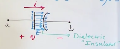
- You have two plates between the terminals not touching each other (in general they have a dielectric (insulator) between them)
- The capaticance is governed by the insulator (i.e. rubber, glass, plastic), the surface of the plates.
- No current is actually flowing between plates, the electrones get stuck at the end of the plate and they charge up that side of the capacitor generating an electric field around the plate.
- Because the positive field attracts the negative electrones at the other side and repels the positive ones, it feels as if the positive electrones are flowing.
- The current through capacitor is \(i(t)=C\frac{dv}{dt}\) with C standing for capacitance.
- While an inductor looks like a shortcircuit in the long-term steady state, a capacitor acts like an open circuit.
- If Voltage has no change, then i = 0
- If the voltage rises, then current is positive (goes in the direction written in the circuit)
- If the voltage falls the current goes in the opposite direction.
- \[v(t) = \frac{1}{C}\int_0^ti(t)dt + v(0)\]
-
\[p=iv\]
- \[p(t)=Cv\frac{dv}{dt}\]
- \[p(t)=i\left(\frac{1}{C}\int_0^ti(t)dt +v(0)\right)\]
- \[w=\frac{1}{2}Cv^2\]
- Capacitor capacitance in series/parallel is the opposite of a resistor resistance:
- In series: \(C_{eq}=\frac{1}{C_1}+\frac{1}{C_2}+\dots\)
- In parallel: Ceq = C1 + C2 …
Natural and Step Response
- Transient response of a circuit: what happens within a short time (charging/discharging process).
- Steady state response of a circuit: what happens past the charging/discharging processes in the long term.
- Natural response of the circuit (discharging): What is the circuit going to do when you give some initial conditions (current, voltage) and then disconnect all the sources and observe the discharge process.
- Step response of the circuit (charging): What happens when we hookup a source to the circuit.
Natural response of an LR (inductor) Circuit
- LR circuit: Circuit with at least one inductor (L) and one resistor.
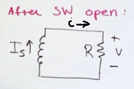
- The switch is initially closed but it opened at t = 0 (so we can assume that the previous state was charged)
- If we leave the switch closed for a long period of time it would reach a steady state, then the inductor would just look like a short circuit
- From t0 onwards we observe how the inducted energy from the inductor L bleeds out to the resistor R, this is known as the discharge process of an inductor.
- SW stands for switch, we want to simplify the circuit into a single LR loop, in this occasion it was just acheived after opening the switch, but sometimes equivalent circuit simplifications will need to be used. This is so we can directly use the punch line to calculate the current rather than having to do new differential equations every time.
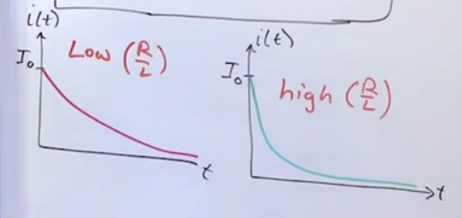
- i(t) decreases as time goes on
- We write a KVL loop with everything in terms of i:
- \(L\frac{di}{dt}+iR=0\)
- \(\frac{1}{i}di=-\frac{R}{L}dt\)
- \(\int_i(0)^i(t)\frac{1}{i}di=\int_0^t-\frac{R}{L}dt\)
- \(\int_{i(0)}^{i(t)}\frac{1}{i}di=\int_0^t-\frac{R}{L}dt\)
- \(ln(i(t))-ln(i(0)) = - R/L (t-0)\)
- \(ln \frac{i(t)}{i(0)} = - \frac{R}{L}t\)
- \(\frac{i(t)}{i(0)} = e^{-\frac{R}{L}t}\)
- \(i(t)=I_0e^{-\frac{R}{L}t}\), for \(t \ge 0\) and with \(I_0=i(0)\), so it decreases exponentially (called exponential decay/natural response of an LR circuit)
- The ratio of R over L determines how fast the current decays
Time constant of an LR (inductor) Circuit
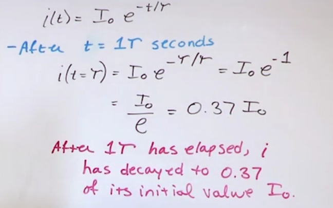
- \(\tau = L/R\)
- After 1T has elapsed, \(i(T) = I_0e^-1 = 0.37 I_0\)
- After 2T have elapsed, \(i(2T) = I_0e^-2 = 0.14 I_0\)
- After k time has elapsed i decays by initial value times \(e^k\)
- When the decay is less than 1% of \(I_0\), such as 5T (which is a thumbrule), we say that the decay is over and that we have reached a steady state.
- The charging process is also exponential and it takes 5T to charge an inductor/capacitor.
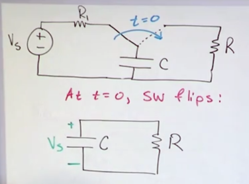
Natural response of an RC (capacitor) circuit
- You can charge/discharge a capacitor exponentially in the same fashion as an inductor.
- In inductors we have \(I_0\) which then bleeds out, here we have \(V_s\) which in the same fashion decreases exponentially.
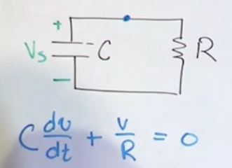
- We can do a KCL in terms of voltage for a node that just connects the capacitor and the resistor and solve for v
- \(v(t)=V_se^{-\frac{t}{RC}}\) for \(t \ge 0\)
Time constant of an RC (capacitor) Circuit
- \(T=RC\)
- After 1T the voltage drop is 0.37 of the initial voltage of the capacitor
- After 5t the voltage drop is less than 1% of the initial voltage value.
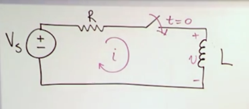
Step response of RL (inductor) circuits
- The current starts flowing at t=0.
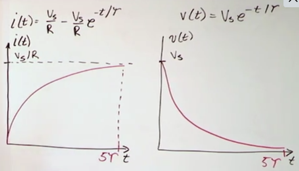
- It raises exponentially until reaching the short circuit current (thus with the resistance of the components in series): \(i(t)=\frac{V_s}{R}+\left(I_0-\frac{V_s}{R}\right)e^{-t/\tau}\) for \(t \ge 0\) and \(\tau = L/R\)
- The voltage drops exponentially (the current increases at a diminishing rate, which means that the inductor “consumes” less overtime):
- \(v(t)=V_se^{-t/\tau}\) for \(t \ge 0\)
- \(v(t)=V_se^{-t/\tau}\) for \(t \ge 0\)
Step response of RC (capacitor) circuits
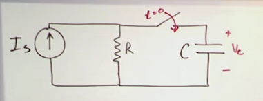
- \(V(t)=I_sR+\left(V_0-I_sR\right)e^{-t/\tau}\)
- Overtime we get an open circuit and the final voltage is the same as the parallel component. \(V0\) is the initial voltage on the capacitor
- \(i(t)=\left(I_s-\frac{V_0}{R}\right)e^{-t/\tau}\)
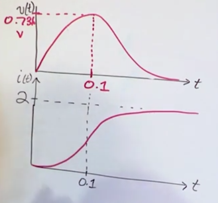
- The shape of the graphs for voltage and i for the capacitor are reversed when compared to the inductor
Op-Amp Circuits
- Op-amp = operational (addition, sign change, scaling, integration, differentation) amplifier
- Building blocks (in the form of integrated circuits) of first analog computers
- Popular Op-Amp \(\mu A\) 741 (or just “741”)
- DIP = dual in-line package (two sets of pins that fit in a breadboard “spine”)
- Symbol = +- triangle
- The numbers are the terminals
- Offset null: used to compensate for the degration of performance overtime.
- Inverting input
- Noninverting input: both inputs 2 and 3 difference is taken as input
- V-: negative power supply
- Nc
- V+: positive power supply
- Output
- Offset Null
Voltage
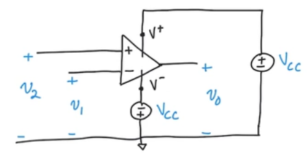
- Vcc = common collector supply voltage (legacy name) = power suply
- All voltage measurements are made relative to the common ground
Current
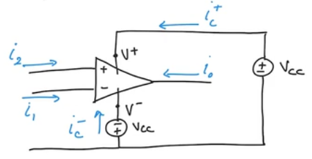
- In reality the currents don’t always go in the drawing direction, but we assume this for the KCLs
Open Loop Voltage Gain
- In practice we can simplify the opamp and implicitly assume the supply voltage
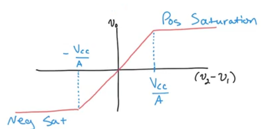
- \(V_{0}=A(V_2-V_1)\), with A as the “gain” and \(V_n\) as output (0), inv-input.
Linear Region
- Region you need to stay such that the gain of the amplifier increases linearly (and work properly)
- \(-V_{cc} \ge V_0 \ge V_{cc}\) or simply \(V_0 \ge |V_{cc}|\) (However know that the positive voltage does not need to be absolutely as large as the negative voltage)
- The output can never be bigger than the supply voltage (otherwise you violate the law of conservation of energy)
- When we reach the flat line (\(V_{cc}\)), it’s called saturation
- Gain A is generally manufactured to be very large (i.e. 10,000)
- Which basically means that you reach saturation very easily with the slightest difference between \(V_2\) and \(V_1\).
Ideal Opamp
- Perfect inputs, outputs, etc.
- Typical opamps use 10V-20V power sources, which with \(10^4\) typical Gain value leaves us with a 2mV = V2 - v1 for the minimum difference to reach the saturation value (opamp then becomes useless for the porpuse of linear amplification)
- Because of this we have the “virtual short” condition, which means that \(v_1 \approx v_2\)
- In an ideal opamp \(v_1 = v_2\) which is like a short circuit because that’s what happens when you have a short circuit (you directly connect two points and hence have the same voltage)
- OpAmps have high input resistance (\(M\Omega\)) or higher.
- an ideal OpAmp has infinite input resistance and therefore \(i_1=i_2=0\)
- Output resistance is equal to zero
- The reason we assume the ideal opamp conditions is to make circuit analysis much simpler (and the final result is still very close to reality)
- KCL: \(i_1 + i_2 + i_0 + i_c^{+} + i_{c}^{-} = 0\)
- \(i_0 = -( i_c^{+} + i_{c}^{-})\)
- This means that (most) of the current of the output comes actually from the supply source (even though its generally not drawn).
- \(V^+ \& V^-\) are often the same, but can be different.
Inverting amplifier circuit
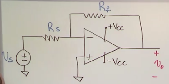
- Rf = feedback resistor
- Rs = source resistor
- \(i_s=\frac{V_s}{R_s}\)
- \(i_f=\frac{V_0}{R_f}\)
Gain
- Because the default configuration has a really large gain (\(10^4\)), we use external resistors in a specific configuration to finetune the desired gain.
- Since \(i_1=0\) -> \(i_s = -i_f\)
- \(\frac{V_0}{R_f}=-\frac{V_s}{R_s}\)
- \(V_0=-\frac{R_f}{R_s}V_s\)
- \(\text{Gain}=-\frac{R_f}{R_s}\)
- The negative sign guarantees that the output will always be negative
- If you dont want to have a negative gain then you can just put two inverting opamps cancelling the sign flip
- To stay linear (and avoid saturation): \(\frac{Rf}{Rs} \lt |\frac{V_{cc}}{V_s}|\)
KCL example
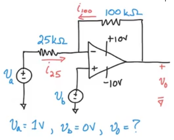
- \(V_2=V_1=V_b=0\) (virtual short)
- \(i_{25}=V/R\) = Difference of voltage before and after (both in relation to ground)/\((25\cdot 10^3)=\frac{1-0}{25\cdot 10^3}=0.04mA\)
- KCL @ inv input: \(-i_{25} + -i_{100} + i_1= 0\)
- \(i_{100} = -i_{25} + 0 =-0.04mA\)
KVL example
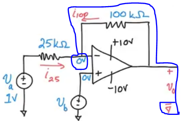
- In an opamp circuit a convinient way to “close” a KVL loop is to start at voltage 0 (commong round) and travel all the way to another common ground (voltage 0) (furthermore it is implied that is a short circuit anyway since it has the same voltage).
- In case of doubt, remember that resistors only have negative voltage drops.
- KVL: \(-V_0 + i_{100}\cdot 10^3 = 0\)
- \(V_0=-4\)
- KVL: \(-V_0 + i_{100}\cdot 10^3 = 0\)
Summing amplifier circuit
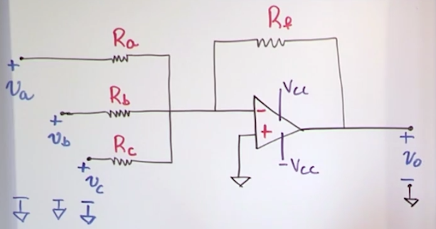
- If it wasnt for Rb and Rc (regarded as inputs) then the circuit would be the same as an inverter circuit
- The output is basically the superposition of each of the inverter opamps with Ra, Rb and Rc respectively.
Example to solve for \(V_0\):
- \(V_0=-(\frac{R_f}{R_a}V_a+\frac{R_f}{R_b}V_b+\frac{R_f}{R_c}V_c)\)
- \(V_0=-Rf(\frac{V_a}{R_a}+\frac{V_b}{R_b}+\frac{V_c}{R_c})\)
- The output will still always be negative.
- Each input has its own gain
- V0 turns out to be IR with I being the sum of the input currents.
- When Ra, Rb and Rc are the same (i.e. Rs): \(V_0 = - \frac{R_f}{R_s}(V_a+V_b+V_c)\)
- If we set \(R_f = R_s\) then the gain is 1 and the output is the inverted (negative) sum of the inputs (with no scaling).
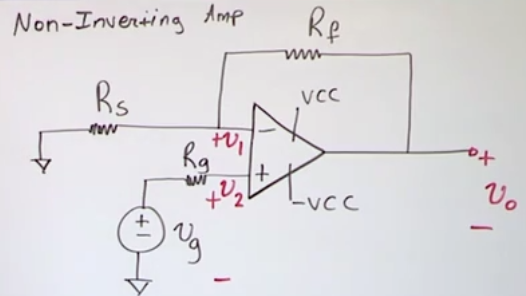
Non-Inverting amplifier
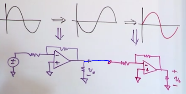
- You can do it by using two inverting amplifier in series
- Or you can do it with just 1 amplifier
- Because the current going into the positive input is 0 and because of the virtual short (perfect opamp assumption) then \(v_2 = v_g = v_1\)
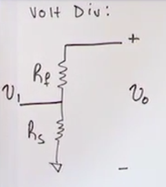
- Then \(v_1 = v_0 \left(\frac{R_s}{R_s+R_f}\right)=v_g\)
- \(v_0=v_g \left(\frac{R_s+R_f}{R_s}\right) = v_g \cdot \text{Gain}\)
- \(\text{Gain} = \left(\frac{R_s+R_f}{R_s}\right) = \left(1+\frac{R_f}{R_s}\right)\)
- We can see that the gain cannot be negative as the resistance of resistors cannot be negative and therefore the input has the same sign as the output.
- The gain is always greater than 1. (the inverting amplifier could make gains smaller than 1)
- For linear operation (to avoid saturation): \(\text{Gain} \le |\frac{V_{cc}}{V_g}|\)
- Because the current going into the positive input is 0 and because of the virtual short (perfect opamp assumption) then \(v_2 = v_g = v_1\)
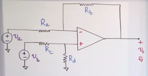
Difference amplifier
- We want to calculate the difference between \(V_a\) and \(V_b\) and amplify it as output \(V_0\)
- NV @ input 1: \(\frac{v_1-v_a}{R_a} + \frac{v_1-v_0}{R_b} + i_1 = 0\)
- Voltage divider of bottom resistors: \(v_2 = v_b \left(\frac{R_d}{R_c+R_d}\right)\)
- Perfect opamp facts: \(v_1 = v_2\), \(i_1=i_2=0\)
- Simplifying & substition of the equations yields: \(v_1=v_2=v_b\left(\frac{R_d}{R_c+R_d}\right)\) and \(v_0=\frac{R_d(R_a+R_b)}{R_a(R_c+R_d)}v_b-\frac{R_b}{R_a}v_a\)
- We can see that the \(v_a\) signal is amplified with a negative sign and with a gain of \(\frac{R_b}{R_a}\) and that the signal of \(v_b\) is positive with a gain of \(\frac{R_d(R_a+R_b)}{R_a(R_c+R_d)}\).
- In general this allows to amplify a and b with different scales.
- In practice you may want to amplify a and b with the same scale, then you apply the constraint: \(\frac{R_a}{R_b}=\frac{R_c}{R_d}\)
- This yields \(v_0=\frac{R_b}{R_a}(v_b-v_a)\), with a gain of \(\frac{R_b}{R_a}\)
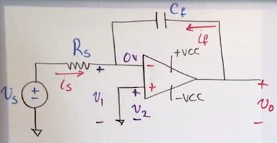
Integrating amplifier circuit
- It’s the same as an inverting opamp except for the feedback resistor that has been changed for a capacitor.
- \(i_f=C_f\frac{dv_0}{dt}\)
- Recall that \(i_s+i_f=0\) and \(i_s = \frac{v_s}{R_s}\)
- \(\frac{v_s}{R_s} + C_f\frac{dv_0}{dt}\)
- …
- \(v_0(t)=-\frac{1}{R_sC_f}\int_{t_0}^{t}v_s(t)dt+v_0(t_0)\)
- if the initial charge on the capacitor is 0 then \(v_0(t_0)=0\)
Common mode rejection ratio
- Measures how much an opamp diverges from the ideal opamp
- The higher the ratio, the more it rejectes common mode signals, the more “ideal” it is.
- Rejecting the common mode signal: Anything common to \(v_1\) and \(v_2\) shall not be amplified (rejected, that is, the gain of the common signals should be 0), recall that in an ideal opamp \(v_0=A(v_2-v_1)\) and when \(v_1=v_2\) then \(v_0=0\)
- In real life \(v_0=A(v_2-v_1)\) is just an approxamition and it’s impossible to manufacture perfectly, so you won’t get that if \(v_1=v_2\) then \(v_0=0\)
- In real life: \(\text{if } v_1 = v_2 \implies v_0 \neq 0\)
- Common Mode Rejection Ratio (CMRR) = \(\frac{\text{Gain of difference of }v_2\ \&\ v_1}{\text{Gain of common mode signals}}\)
- \(CMMR=\frac{A_d}{A_c}\), you want \(A_d\) to be high (it should approximate A) and \(A_c\) to be low (it should approximate 0).
- CMMR is usually \(10^3\) to \(10^6\) and it is usually expressed in decibels
